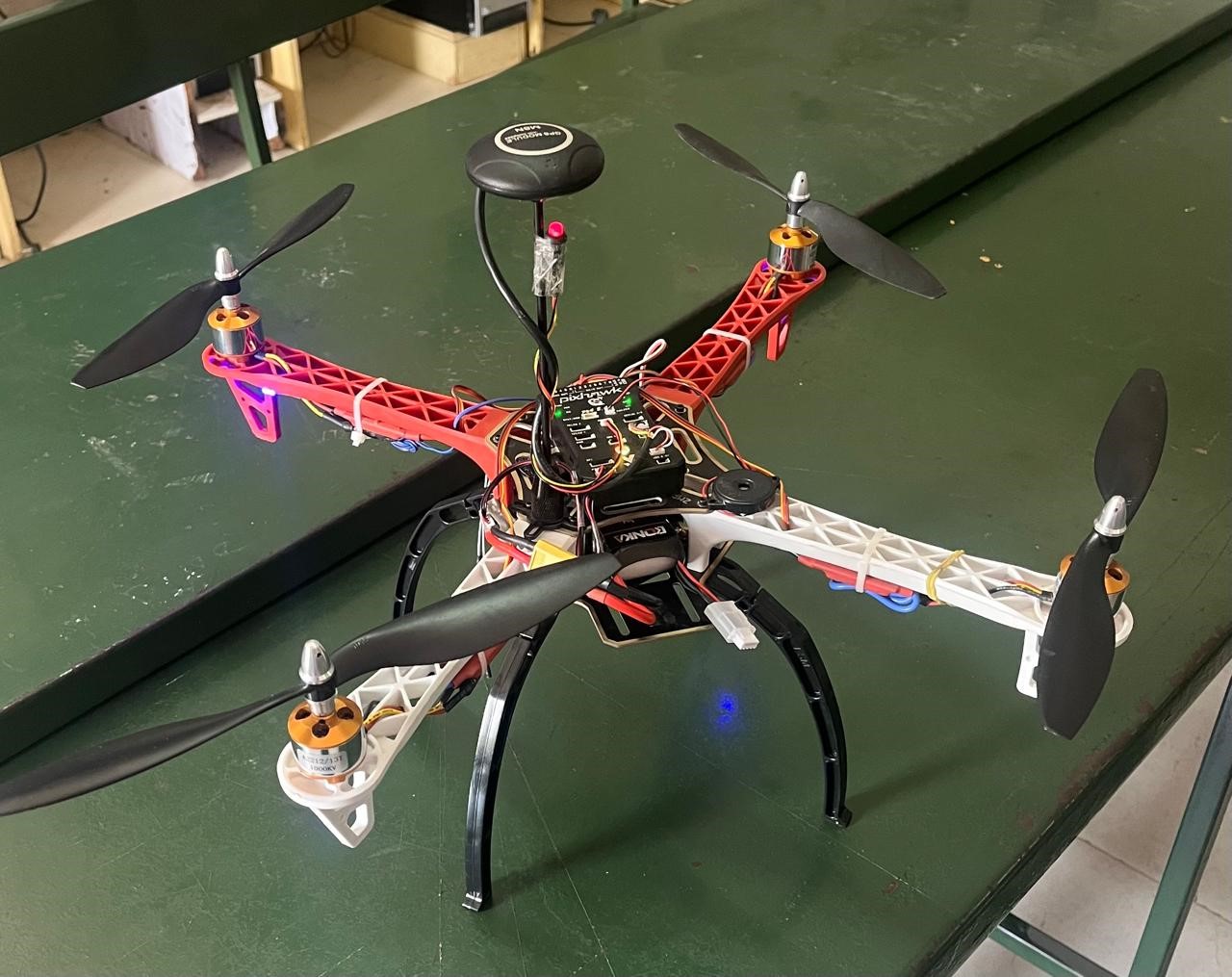
A quadcopter is a multirotor drone with four arms or booms, each with a rotor (hence “quad copter”). Multirotor drones are unmanned aerial vehicles (UAV) with multiple rotors that are used to generate lift to enable the aircraft to fly. Many of these aircraft are Unmanned Aerial Vehicles, or UAVs, meaning they are self-flying or autonomous. Some of the aircraft controlled in the AAM system are quadcopters, similar to commercially available drones. The term quadcopter refers to the fact that they use four propellers to fly.
Our project involves deploying AI-equipped drones for search and rescue operations. These drones use thermal imaging and AI-powered object detection to locate survivors in disaster-affected areas efficiently. They can quickly map large regions and provide real-time data to rescue teams, improving response times and accuracy. Additionally, drones can access areas that are difficult or dangerous for human rescuers to reach, enhancing overall mission safety and effectiveness.
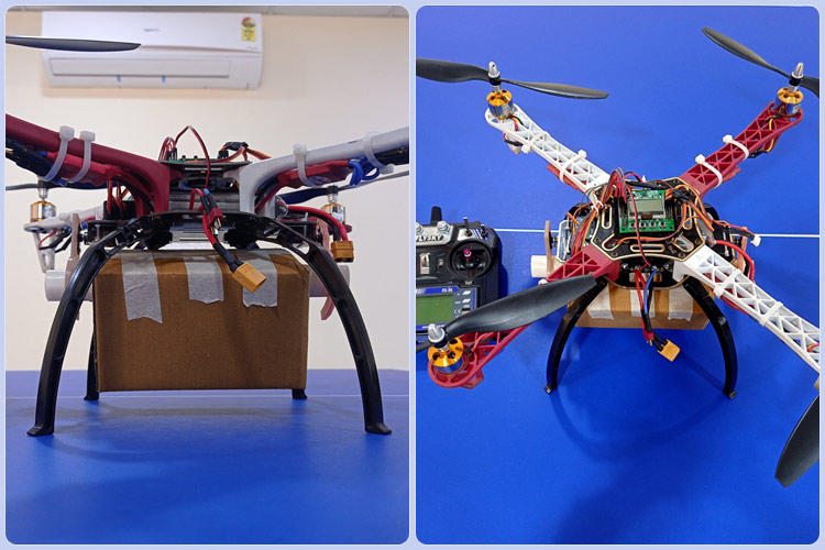
The drone delivery project involves designing and building a drone equipped with a carrying box that features an automatic open-close door mechanism controlled by a servo motor. The drone, constructed with a lightweight yet sturdy frame, is powered by brushless DC motors and a Li-Po battery, and includes a flight controller with GPS for stable navigation. The carrying box is securely attached to the drone. The door mechanism is hinged and controlled by a servo motor, which receives commands from the flight controller or a microcontroller to open and close at the appropriate times. During delivery, the drone navigates to the target location, where the door opens to release the package and then closes before the drone returns to base.


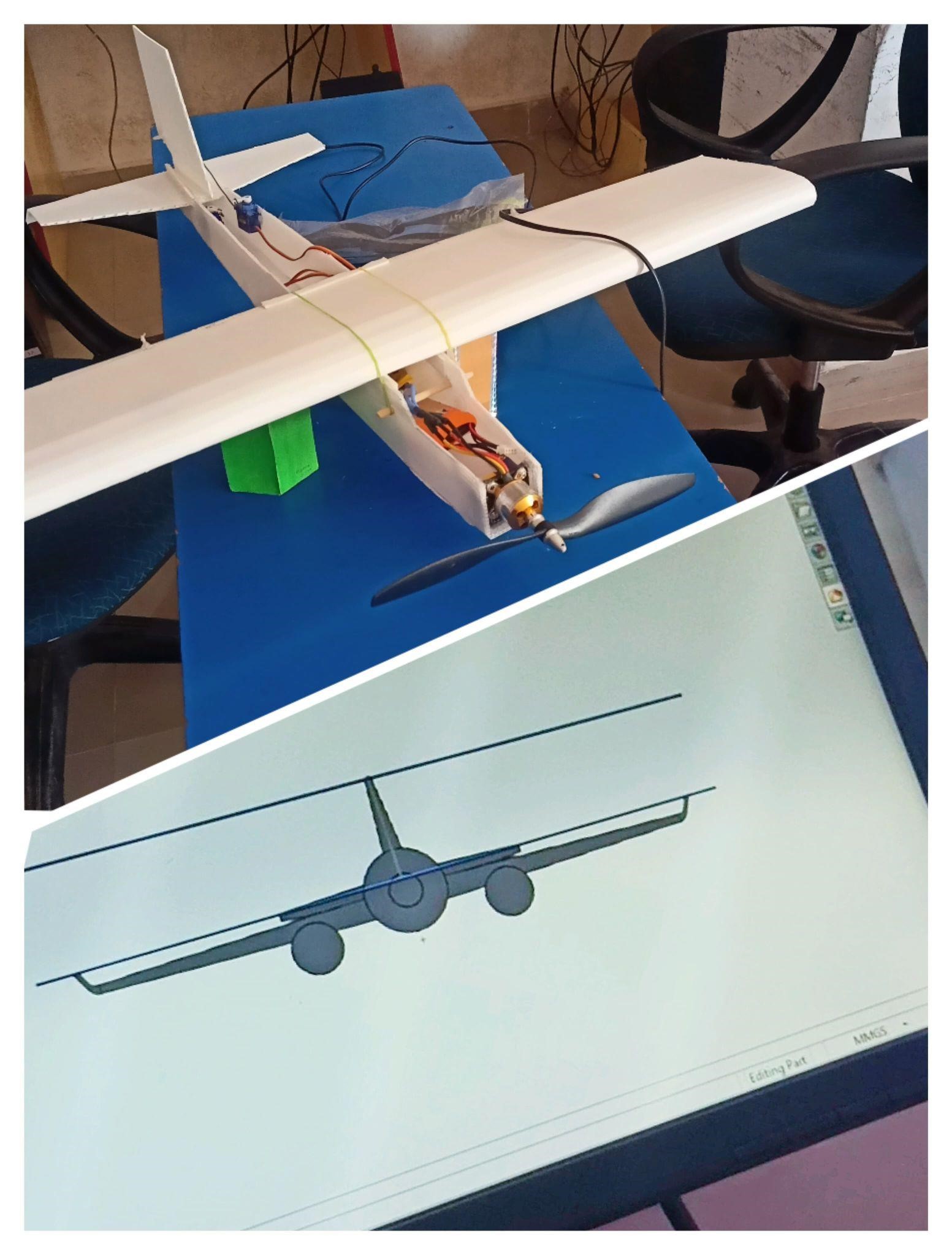
Designing and fabricating an RC aircraft using SolidWorks involves a systematic process that begins with determining the aircraft's specifications, including its purpose, dimensions, and type. In SolidWorks, the design process starts by creating individual components such as the fuselage, wings, tail section, and control surfaces, using sketch and extrusion tools. These components are then assembled, with proper alignment and mating features, and integrated with fasteners and joints. Simulation tools within SolidWorks, such as Finite Element Analysis (FEA) and aerodynamic simulations, help optimize the design by assessing structural integrity and airflow. Once the design is finalized, technical drawings are generated for fabrication. The fabrication process includes selecting materials like balsa wood, plywood, or carbon fiber, and cutting to precisely shape parts. 3D printing may also be used for components like motor mounts or landing gear struts. Manual assembly follows, where parts are bonded using appropriate adhesives, and electronics such as motors, servos, and receivers are installed. Control linkages are connected, and the aircraft is covered with heat-shrink film or painted for finishing.